The light
The standard light intensity is set at 500Lux horizontal and 200Lux vertical data centers.
Lighting locations are within one meter of the floor between the racks.
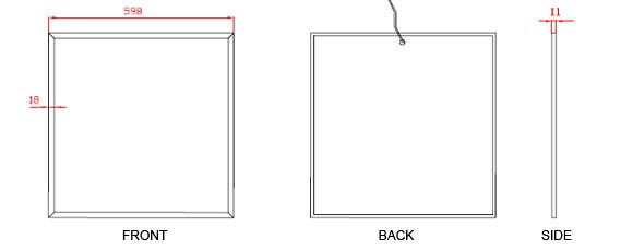
LED has a very delicate appearance and is very thick and is made with SMD LED technology based on LED display technology and creates a perfectly smooth and smooth light without glare. It should be noted that each of them produces very little electricity and very little heat. The dimensions of the LED frames are 61 * 61cm which are installed inside the false ceiling.
• A number of lights must remain on during emergency room power outages.
HVAC cooling system
The environmental conditions of the data center are as follows:
• Optimum temperature: 18 to 24 ° C
• Minimum temperature limit of 17 and maximum 25 ° C
• Optimal humidity: 40 to 55%
• Minimum permissible humidity of 30% and maximum of 60%
• Maximum dew point temperature: 21 ° C
• Maximum temperature change in one hour: 5 ° C
Measurements should be made within 1.5 meters of the floor in the middle of a cold path between two rows of racks.
It is recommended that the data center has an independent cooling system. Equipping the HVAC cooling system with a backup power supply is also required.
Distribution methods
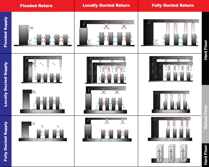
The mechanism of the high-capacity data center cooling system is distributed and recursive. For each mechanism, there are three main methods:
• Flooded:
In the Flooded solution, the distribution or recirculation system distributes or collects airflow without any specific docking.
• Locally Ducted:
In a locally ducted solution, airflow is distributed and collected through the duct near the hot or cold corridor, depending on the distribution or recirculation system.
• Fully Ducted:
In the Fully Ducted Solution, the distribution and collection system distributes or collects air directly, through a closed route of hot or cold aisle.
Each of these methods can be used in combination with the distribution or collection system. This will create 9 different ways. In the following figure we can see each of the combined methods:
Types of server room air conditioning
Relatively older servers have a power consumption of about 1,200 W and can be cooled using standard HVAC or CRAC (Computer Room Air Conditioner) coolers. These types of coolers send the generated cool air from underneath into the space below the false floor and cool the existing servers through the hinges installed on the false floor. The hot air is returned to the CRAC via the return channel (if any) and the cycle repeats itself with advances in server technology and shrinkage and introduction of blade servers, although the cost of building these servers has not changed significantly in the past. But their electricity consumption and heat generation have increased dramatically. Therefore, more precise arrangements should be made to cool them.
• In-Room Method
A conventional CRAC device sits on a false floor and draws warm air in from the upper part, directing it to the false floor after passing through the heat exchanger and cooling. In devices manufactured by some blower fan makers, the fan is moved to the device under the false floor area, thus leaving the fan vacant and increasing the dimensions of the heat exchanger. As a result, cooling capacity can be increased with the same dimensions. For example, using this method you can expect up to 30 kW of cooling power from a device that has a conventional power of 20 kW. These types of coolers provide two types of cool air. In the first case, the machine itself has a compressor and sends refrigerant gas to the condenser. In the latter case, the device is connected to the chilled water cooling pipe system. In this pump system, it is responsible for the circulation of cold water in the cycle. Therefore, due to the removal of the compressor from the device, the dimensions of the heat exchange network can be dramatically increased and increase the capacity of the devices.
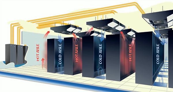
• In-Raw method
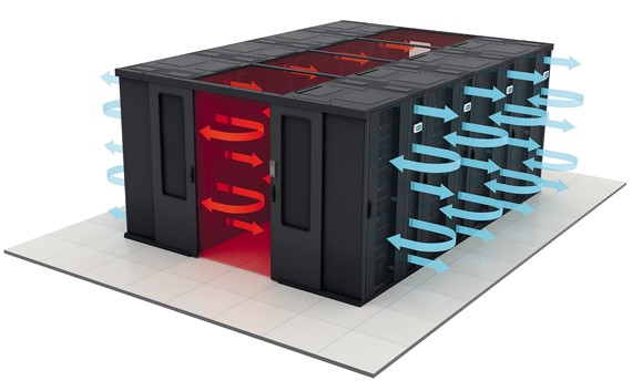
In this way, the racks are aligned in several parallel rows to prevent hot and cold air from mixing in the server room. The rack is mounted in such a way that the racks in front of each rack are in one direction and the two adjacent rows are arranged in such a way that the front or back of all racks are facing each other. Therefore, in an aisle, air is sucked into the racks and in the adjacent corridors hot air is sent from the racks into the aisle. So there are two types of corridors: the warm corridor and the cold corridor. To make sure that the hot and cold air does not interfere, two adjacent corridors can be completely separated from each other by means of roof and front and end door components.
• In-Rack Method
By increasing the cooling power required in a rack, it can no longer be completely cooled by the methods described above. In this case, due to the high heat generation density in the racks, cool air is sent directly into the rack by special blowers. These blowers use cool water produced by chillers.
It can also blow cold air from either side (or two racks), or you can install two cooling devices for one rack and consider one of these as an extension.
• In-Raw method
In this way, the racks are aligned in several parallel rows to prevent hot and cold air from mixing in the server room. The rack is mounted in such a way that the racks in front of each rack are in one direction and the two adjacent rows are arranged in such a way that the front or back of all racks are facing each other. Therefore, in an aisle, air is sucked into the racks and in the adjacent corridors hot air is sent from the racks into the aisle. So there are two types of corridors: the warm corridor and the cold corridor. To make sure that the hot and cold air does not interfere, two adjacent corridors can be completely separated from each other by means of roof and front and end door components.
• In-Rack Method
By increasing the cooling power required in a rack, it can no longer be completely cooled by the methods described above. In this case, due to the high heat generation density in the racks, cool air is sent directly into the rack by special blowers. These blowers use cool water produced by chillers.
It can also blow cold air from either side (or two racks), or you can install two cooling devices for one rack and consider one of these as an extension.
HP IN RACK Cooling System
By increasing the cooling power required in a rack, it can no longer be completely cooled by the methods described above. In this case, due to the high heat generation density in the racks, cool air is sent directly into the rack by special blowers. These blowers use cool water produced by chillers.
It is also capable of blowing cold air from either side (or two racks) or can be mounted on one rack with two cooling devices and one of these devices considered as an extension.
Method of calculating the data center cooling power required
Below is the formula for calculating the cooling power of HVAC systems.
Cold production for the effective operation of servers, routers, switches and other key equipment is one of the most important parameters of a server room and data center. A malfunction or malfunction of the air conditioner can have serious consequences for the organization, so don't be indifferent to your server room air conditioning system. Using alternative warning systems can be a good way to prevent these consequences. But first and foremost, accurately calculating the amount of air needed is the most important thing to do.
Introduction to several concepts:
BTU (British Thermal Unit): The unit of heat energy measurement in the cooling and heating industries. In the definition of each BTU, it is the amount of heat that brings the temperature of a pound of water at atmospheric pressure, from 60 degrees Fahrenheit to 61 degrees Fahrenheit.
WATT: The unit of measurement of power is 3.413 BTU.
Ton: The power required to create a piece of ice is 907Kg in 24 hours. And is equivalent to 12000BTU or 3.5KW.
Effective parameters:
Room Area
Room Area BTU = Length (m) x Width (m) x 337
If your server room does not have a window, you can skip this section otherwise:
South Window BTU = South Facing window Length (m) x Width (m) x 870
North Window BTU = North Facing windows Length (m) x Width (m) x 165
If there is no obstacle on the way to the windows and the direct sunlight shines through, finally multiply the numbers by 5.1. Obviously, if you live in the Southern Hemisphere, you have to change the values in the North and South Window formulas.
Occupants
Total Occupant BTU = Number of occupants x 400
Equipment
Equipment BTU = Total wa_age for all equipment x 3.5
Lighting
Lighting BTU = Total wattage for all ligh_ng x 1.75
Finally, the total required cooling is calculated from the sum obtained in each section:
Total Heat Load = Room BTU + Windows BTU + Total Occupant BTU + Equipment BTU + Lighting BTU
mohsen hakimi, [۱۸.۰۸.۱۹ ۱۴:۱۶]
Power Distribution System
The most important and sensitive part of any data center design is the complete planning of the power supply, especially the power supply of IT equipment. Capable of supporting all center equipment with proper and complete infrastructure. In designing a data center according to the level of the tire required, the designed power system must be as low as possible for the equipment to be cut off, and sufficiently secure to supply and distribute the required electrical energy. Therefore, before designing, the information needed to design the power system must be collected, the most important of which are:
• Power consumption of individual equipment
• Estimate the power required by the data center
• Schematic design of the overall data center power grid
• Designing a single line map of data center power boards
• UPS data center power grid design (UPS required load estimation, UPS sizing, associated power panel design)
• Sizing diesel generator for data center and building
• Design of a data center ground network
• Data center lighting network design
Designing a power grid in a data center consists of five sections:
• UPS (Uninterruptible Power Supply System)
Sudden power cuts in server room equipment, such as routers, switches, servers, and the activities of these devices, and in some cases, completely eliminate the ability to continue working. It should be borne in mind that the mere power outage of the city has no detrimental effects. Computer systems are sensitive to failures such as instantaneous voltage drop, high instantaneous voltages, noise and radio frequency effects, and frequency changes in their power supply.
A suitable UPS has the following conditions:
1-. Online Double Conversion
2- Support Power Factor Correction. That is, it is capable of working with a generator.
• Air
In order to protect people and devices, the excess voltage generated in the body that damages the devices and individuals, as well as the extremely high voltage hazards caused by lightning, should be offset somewhere. For this reason, the use of earthing systems and equipment protection is essential, and with the increasing use of digital and sensitive systems, there is a need to rethink the design, installation and maintenance of grounding protection systems.
In short, the goals of using an earthing or earthing system are:
A. Protection and safety of human life
(B) The protection and safety of electrical and electronic equipment and supplies
Providing ideal working conditions
D) prevent contact voltage
E) Remove excess voltage
And ـ Prevent unwanted and lightning voltages
G) Ensure electrical work capability
Wells:
The earth or earth system must be located to prevent excessive and damaging loads on the electrical system.
Standard ground well conditions:
* Well drilling must be done until it reaches saline soil.
* Coal and salt (sodium chloride) powder in a ratio of one to two (Hercules, two kilos of salt) to 40 kg in the well (these materials are inversely proportional to the soil and increase or decrease the soil strength. Or low returns).
* Copper plate 50 * 50 cm in diameter and 1 cm in diameter (vertical) blade on salt and charcoal.
* Copper wire 50 mm in diameter is attached to copper plate by copper wire and copper special bolts to prevent rust and rust.
* Polycarbonate pipe 4 or 6 cm in diameter is installed next to each well. It is important to note the numerous holes in the body of Lu